
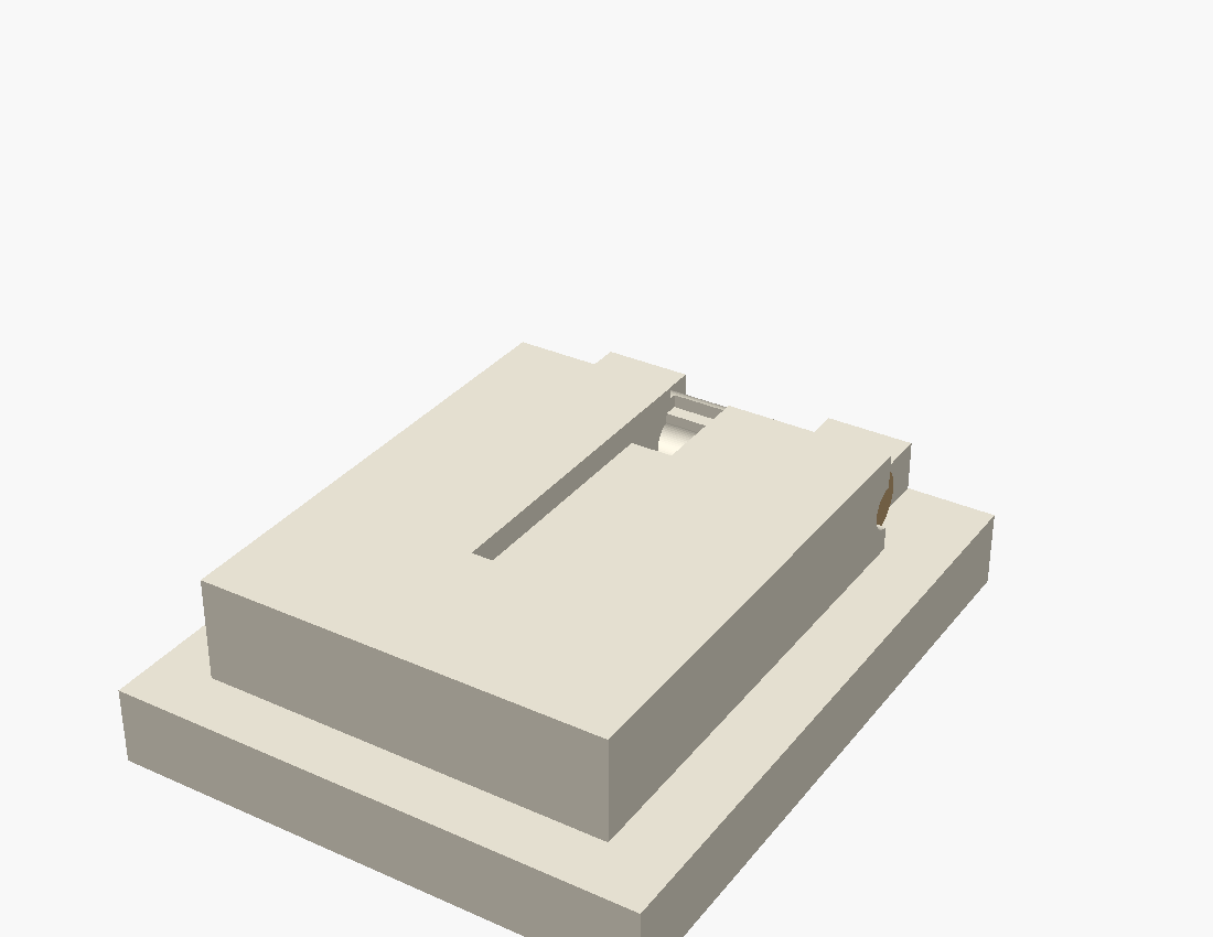
A tiny USB-powered status display: a 0.96" OLED on a friction-hinged pod that
stands up to read and folds flat onto a serviceable base. This is the first-proof hinge + wire-path
coupon (v0.2) — the riskiest interface reduced to two printable parts. Geometry only;
unproven until the bench.
drag to orbit
110°
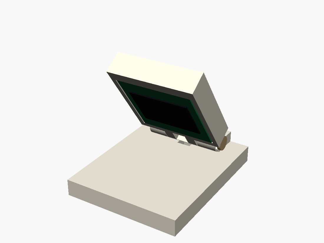
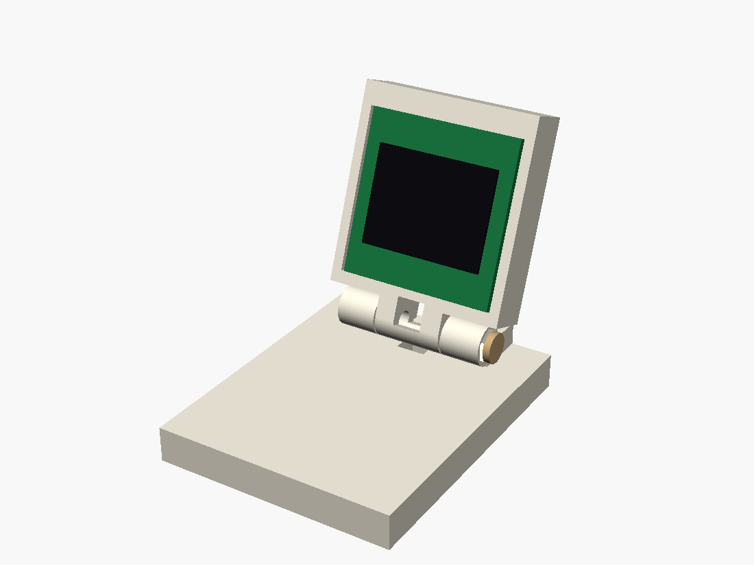
FIG · live the assembled coupon with hardware — the 0.96" OLED
rides in the pod, the ESP32-S3-Zero in the base. Drag to orbit; slide or hit ▶ to fold it
flat → reclined back ~110° to view. Collision-free across the whole sweep (the GIF is the fallback if 3D won't load).
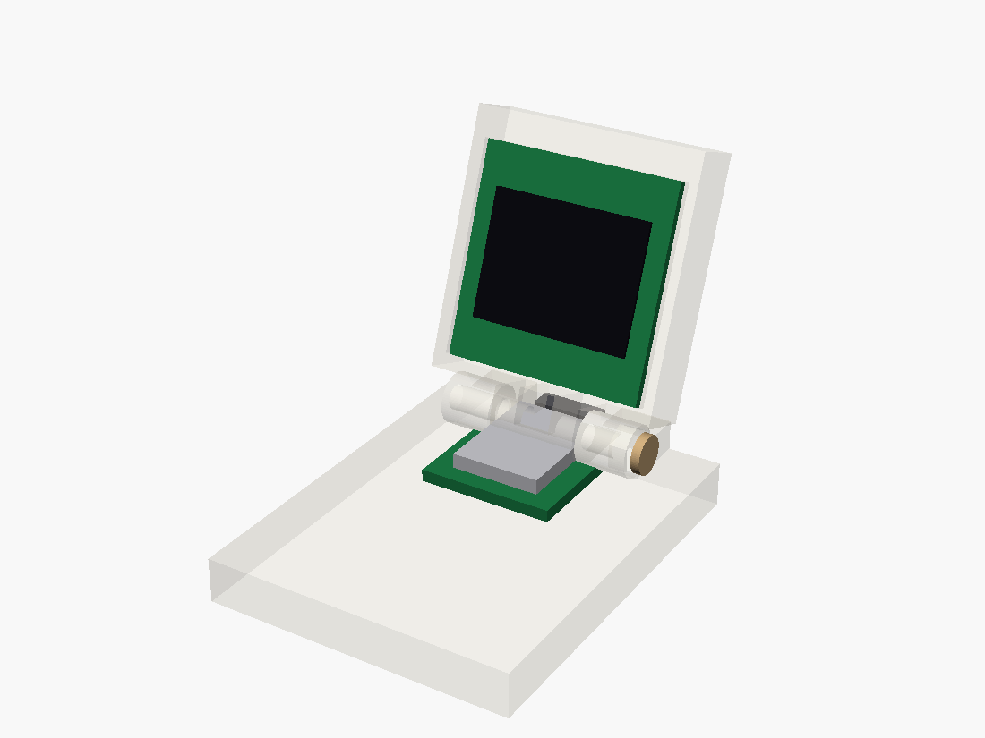
FIG · the hardware shells ghosted: the 0.96" SSD1306 OLED
rides in the pod, the ESP32-S3-Zero in the base (raised here for clarity), the interleaved M3
knuckle hinge between. Soldered leads cross at the hinge axis.
display
0.96" OLED 27×28 mm, active 21.74×10.86, +1.92 offset
geometry only · unprovenv0.2 · 7 gates green (incl. swept-collision + ear-wall) · the print is the proof:
friction hold, lead survival, and horizontal-barrel printability are bench items
The whole object reduces to one hard question: can a printed friction
hinge hold a screen up, fold flat, and route the OLED leads without crushing them? So the first
proof isn't the enclosure — it's a cropped pod stub + base cradle + the real M3
hinge, modeled on the calipered ESP32-S3-Zero and 0.96" OLED references.
It took two adversarial review cycles to make it real. The first caught
the pod slab sweeping straight through both base knuckles for the entire
fold — green gates and a clean render had both missed it. The fix (relieve the slab, supports to the rear)
introduced a 1.05 mm-thin hinge ear, which the second cycle caught. Each
blind spot earned a computed gate — a swept-boolean for the collision, an ear-wall check for the thin
fin — so neither failure class can hide again. A render is never a fit; a green gate is never a print.
The base · where the hardware lives
…and the USB-C cutout
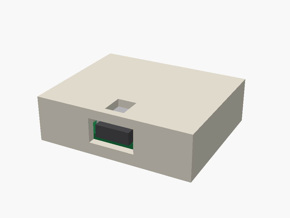
The hinge coupon had no port — so here is the real base: the
ESP32-S3-Zero in a serviceable shell with a rear USB-C notch aligned to its port, a bottom plate
that carries and releases the board, and the hinge cradle at the back. Drag to orbit; it opens facing the rear
so the port reads (the shell is ghosted so you can see the board).
drag to orbit
USB-C ▸ rear
FIG · the base ESP32-S3-Zero (green) in the cavity, its USB-C seated in the
rear-wall notch at port height; the bottom plate carries the board (service from below); hinge cradle + nut boss
at the rear-top.
geometry only · unprovenUSB-C notch aligned for a direct/soldered board. Two print-readiness review cycles
fixed a 148 mm³ post/plate overlap, a 0.32 mm nut wall, and sub-min-wall pockets — now guarded by a real
mesh gate. Open fork: the closed top deck bridges 37 mm → needs print support or a service-direction
redesign; the matching pod is modeled below.
The payoff · two proofs, one product
The whole thing — folded and open
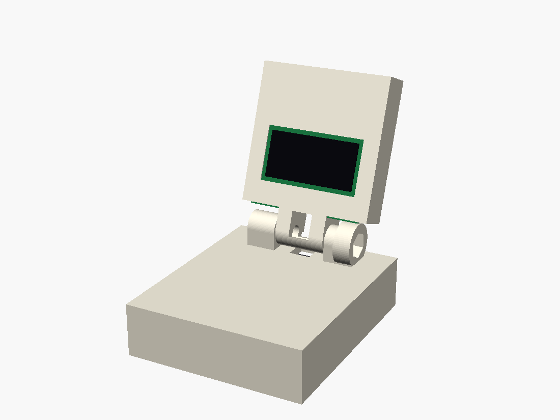
The hinge coupon and the base were separate proofs at different
hinge heights. The matching pod re-bases the proven pod onto the real enclosure hinge so they finally go
together as one object. Drag the slider — it reclines back to ~110° so the screen tilts up toward you, then folds flat to stow. Pod,
base, ESP32 and OLED are all here.
drag to orbit
110°
FIG · unified product base + matching pod on the M3 friction hinge; the OLED
(screen biased +1.92 toward the hinge) faces the user when open, folds flat onto the apron. prod_swept_collision
= 0 across the whole fold.
geometry only · unprovenThe tapered pod neck threads between the base knuckles — the first full-width cut rammed the
pillars + nut boss, caught by a real swept-boolean gate at 64 mm³ and fixed to 0. A solid-slab integration proof;
the open-back pod shell + OLED screw capture is the next refinement. Needs a print.