iron body
19.5 × 17.5 mm, flat top
Field note · fit & tolerance
A MakerWorld stand insert for the FNIRSI HS-02B was loose on my HS-02A in both grip zones. I re-cut the two inner seats it grips, and moved not one point of the exterior, so it still drops into the existing stand. It is not finished, and this note says so.
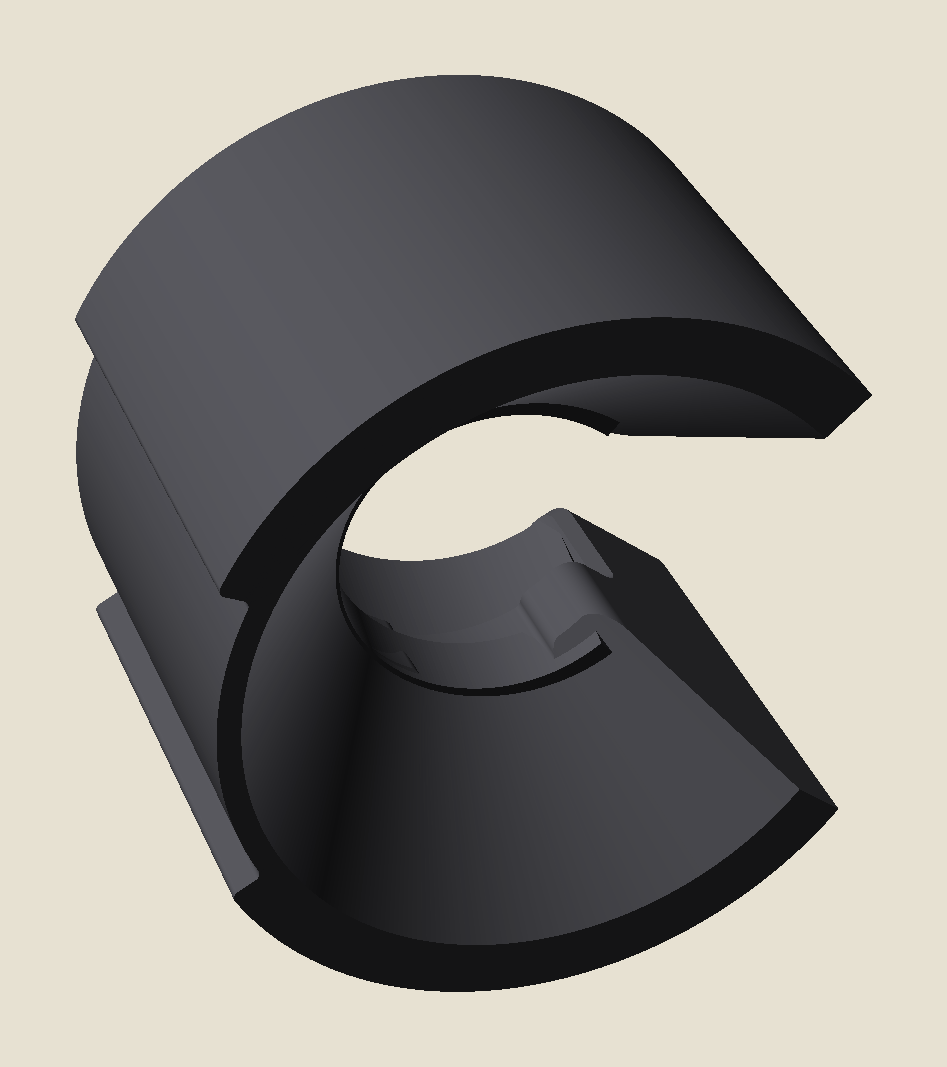
The part is a swappable insert from a modular USB-C soldering-iron stand. The handle snaps into a C-clip cradle; the cradle's outer shell and two rib grooves register it into a common base. The catch: I downloaded the version cut for the HS-02B, and I own the HS-02A. FNIRSI's manual claims the two share a shell. The wobble in my hand claimed otherwise, and the part shipped as an STL only, no parametric source. So this is a mesh edit with one hard rule: tighten the inside, touch nothing the stand mates to.
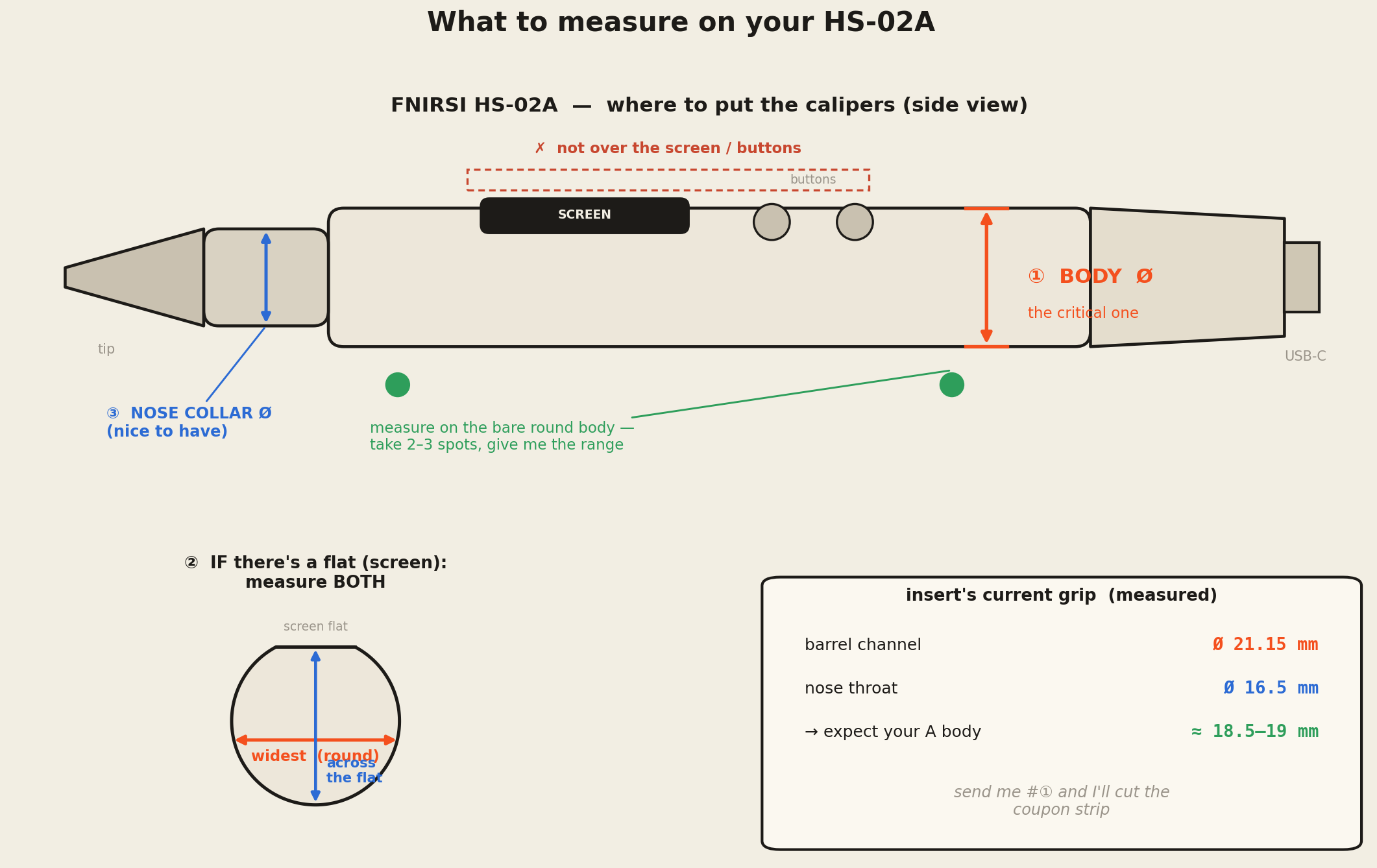
Calipers first. The body is a Ø19.5 cylinder with a ~2 mm flat milled for the screen; the nose collar behind the tip is 16.4 mm. The stock insert's seats measured Ø21.5–24 at the body and Ø16.7–17.7 at the nose: loose by 1.6–3.6 mm and 0.3–1.3 mm. The spec sheet said "same shell." The part in my hand disagreed, and the part in my hand is the ground truth.
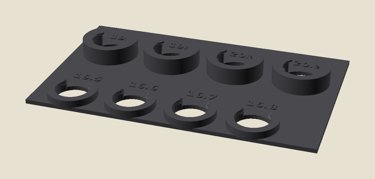
Reprinting the whole insert per guess is wasteful, so I cut a fit coupon: a strip of clip sections at swept seat diameters. Print it, feel which one grips right, bake that number in. Good plan. Then the result felt wrong, and the reason was mine.
I'd bored a clearance hole through the coupon base +1.2 mm oversize. When the iron was pushed in from below, it sat in that sloppy hole, not the seat above it, reading ~1 mm looser than reality. A coupon whose answer depends on which way you hold it is a broken instrument.
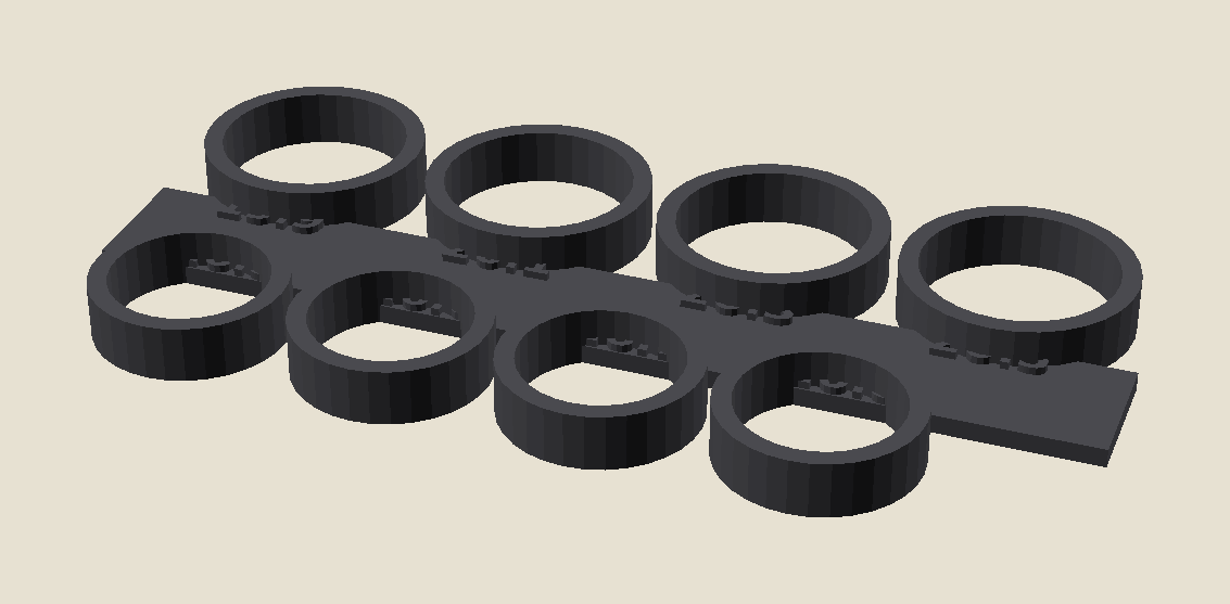
For a pure diametral fit (grip set by diameter alone), only the innermost wall sets the result, so the chunky clips were mostly wasted plastic. I replaced them with a thin-ring gauge: full rings at the swept IDs on one labelled spine. Same fit, a third of the print. And because a full ring is symmetric, it reads the same from either end, which is exactly the ambiguity that bit me in step 02, designed out.
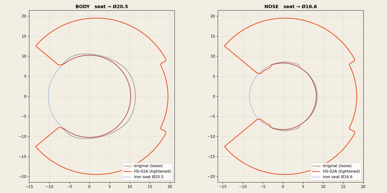
The change is two conformal liners added on the inner wall arc, clear of the snap mouth, bringing each seat down to its target. Nothing is subtracted; material is only added, only on the inside.
Before claiming anything, I ran the part through a print-readiness gate built to disprove "ready." It earned its keep: it caught two real mesh defects I'd glossed, and it refused to call the fit proven.
| Check | Verdict |
|---|---|
| Outer shell identical, material added inside only | pass |
| Seats measure Ø20.5 / Ø16.6 | pass |
| Mesh watertight (2 degenerate facets at the boolean seam) | caught → fixed |
| Gauge a clean single body (41 loose shells) | caught → fixed |
| Fit confirmed on the real iron | unproven |
The one requirement that can't be "close enough": the outer shell has to be the original, or it won't seat in the stand. So I measured it, both directions. Isolating the exterior surface and running a bidirectional Hausdorff distance (the largest gap between the two surfaces, checked in both directions) against the original gives 0.0000 mm each way, across all 1,750 shell vertices. The only geometry that moved anywhere in the part is the two inner seats. It drops into the stand exactly as the original did.
Exterior deviation, original ↔ refitted: max 0.0000 mm, both Hausdorff directions. A boolean re-tessellated the triangle mesh (75k → 55k faces), but the surface is the same surface. Triangles changed; geometry didn't.
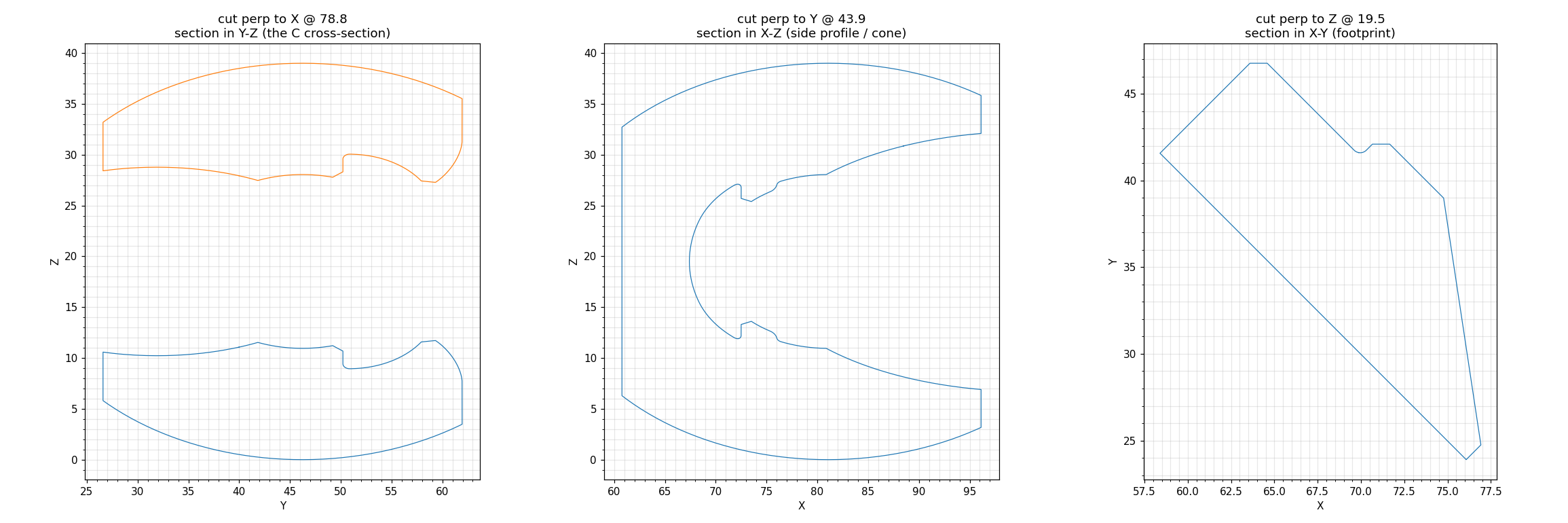
Honestly: still not done, but several prints further than this note's first draft. The body grip got dialled off real irons (v1 Ø20.5 too tight → v2 Ø20.7 good but a touch snug → ~Ø20.9). Along the way the liner picked up shapes the stock part never had: a flat shelf at the rim, then an imposed constant-diameter cylinder where the stock seat is a gentle taper. v4 throws those out: it fits a clean line to the stock contour and shifts it just inward, so each seat is a taper that parallels the original, keeping the deep grip (body ~Ø20.9) and easing open toward the mouth exactly like the stock part. Outer shell proven identical to the printed v2 to 0.0008 mm and the rim back to the stock's own profile, so it still drops into the stand. The grip number is still one hand-judged read off a print, so the part stays provisional until v4 is printed and the HS-02A is dropped into it.